Inverter Wiring Diagram

Ups Inverter Wiring Diagram For One Room Office Electrical Online 4u Electrical Tutorials House Wiring Electrical Wiring Circuit Diagram

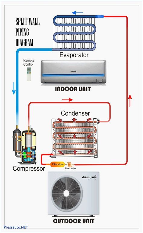
Diagram Diagramtemplate Diagramsample Refrigeration And Air Conditioning Electrical Circuit Diagram Ac Wiring

New Inverter Wiring Diagram Pdf Diagram Electrical Wiring Diagram Diagram Design

Manual Auto Ups Inverter Wiring Diagram With Changeover Switch In 2020 Electrical Circuit Diagram Electrical Wiring Diagram Diagram

Wiring Diagram Ac Sharp Inverter New Washing Machine Circuit Diagram Pdf Wiring Diagram Update Washing Machine Motor Circuit Diagram Washing Machine Whirlpool

Image Result For Rv Converter Charger Wiring Diagram Buy Solar Panels Solar Power Inverter Solar
A diagram shows how to properly wire a charge controller and an inverter into the same battery based pv system.
Inverter wiring diagram.

Sine Wave Inverter Circuit Diagram The Wiring Diagram Circuit Diagram True Sine Wave Inverter Circuit Diagram Rangkaian Elektronik Elektronik Teknologi

1kva 1000 Watts Pure Sine Wave Inverter Circuit Electrical Engineering World Electronic Circuit Projects Circuit Diagram Circuit Projects

Wearing Diagram Ups Wiring Inverter Wiring Diagram For Single Room Electrical With Inverter Home Wiring House Wiring Electrical Circuit Diagram Circuit Diagram

Inverter Circuit Diagram 5000w Agendadepaznarino Com Circuit Diagram Circuit Projects Electronics Circuit

Homemade Circuit Projects Make This 1kva 1000 Watts Pure Sine Wave Inverter Circuit Electronic Circuit Projects Circuit Diagram Circuit Projects

Inverter Connection Diagram Install Inverter And Battery At Home In 2020 Electrical Circuit Diagram Electrical Wiring Diagram Electrical Diagram

Cd4017 100 Watt Inverter 12dc To 220ac Circuit Diagram Power Inverters Electronics Circuit

How To Make Solar Inverter Circuit Solar Inverter Circuit Diagram Solar

New Inverter Wiring Diagram Pdf Ac Wiring Electrical Circuit Diagram Electrical Wiring Diagram

Automatic Ups Inverter Wiring Connection Diagram To The Home Ups System Electrical Circuit Diagram Circuit Diagram

Pin On Homemade

Inverter 5000 Watt Pwm Power Inverters Electronic Schematics Acdc

5kva Ferrite Core Inverter Circuit Full Working Diagram With Calculation Details Elektronnaya Shema Elektrotehnika Elektronika

30 Amp Rv Plug Wiring Diagram Inspirational Wiring Diagram For Rv Inverter Best 50 Amp Wiring Diagram Refer Trailer Wiring Diagram Electrical Wiring Diagram Rv

Pwm Sinewave 5kva Inverter Circuit Circuit Diagram Circuit Projects Electronics Circuit

How To Connect Automatic Ups Inverter To The Home Supply System House Wiring Ups System Home Electrical Wiring

Automatic Ups Inverter Wiring Connection Diagram To The Home Ups System Electrical Circuit Diagram Home Electrical Wiring

Este Es Un Simple Diagrama De Circuito De Inversor De 2kva Y Puede Usarse Para Alimentar Un Refrigerador Y U Circuit Diagram Electrical Circuit Diagram Diagram
Https Encrypted Tbn0 Gstatic Com Images Q Tbn 3aand9gcqm6q98a3zimbzr 76iiyhxtijykkgcg Gfxgywwgnbgbhmtzpp Usqp Cau

Automatic Ups Inverter Wiring Connection Diagram To The Home In 2020 Ups System Electrical Circuit Diagram Home Electrical Wiring

Electronic Circuit Projects How To Build A 400 Watt High Power Inverter Circuit With Bui Electronic Circuit Design Electronic Circuit Projects Power Inverters

Wiring Diagram Ac Sharp Inverter New Wiring Diagram For Air Conditioner Wiring Library Sharp Air Conditioner Hvac Tools Conditioner

Welcome This Is A Simple 24v Dc To Ac Inverter Circuit Diagram By Freeborn Emm Circuit Diagram Electrical Circuit Diagram Diagram

Pin On Inverter Circuits
Source : pinterest.com
